
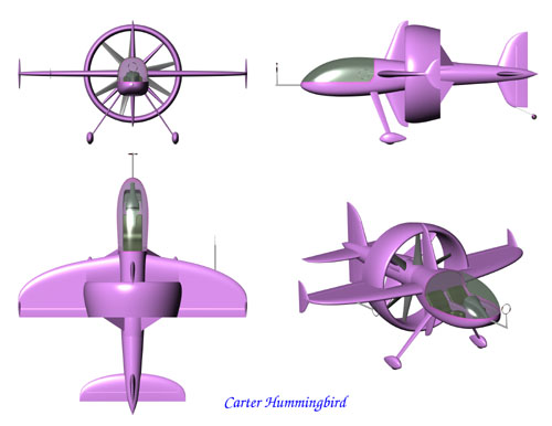
Configuration
Wing
Engines and Propellers
Cockpit and Canopy
Tail Surfaces
Aft Fuselage
Landing Gear
Two Place Configuration
Before addressing detailed aerodynamic and structural issues, it is helpful to briefly review the rationale behind Hummingbird’s configuration. The configuration follows naturally from the following requirements:
- A propeller shroud (duct) is to be incorporated, along with counter-rotating propellers and engines.
- The duct is to be configured so as to function as an annular lifting surface and as a wing brace.
- The aircraft is to be aerodynamically symmetrical.
- To minimize mass inertias, all heavy or rotating components (engines, propellers, pilot) are to be located near the aircraft center of gravity.
- For control (with power) at low and zero airspeeds, tail surfaces are to be located in close proximity to the propellers and centrally in the propeller wash.
- The pilot is to be provided with exceptional visibility and attitude reference.
Starting with these requirements a new configuration has been devised which promises to be optimum for aerobatics.
Duct
The duct is the aerodynamic, propulsive, and structural heart of the airplane. Therefore we begin with the duct and configure the remainder of the airplane around it.
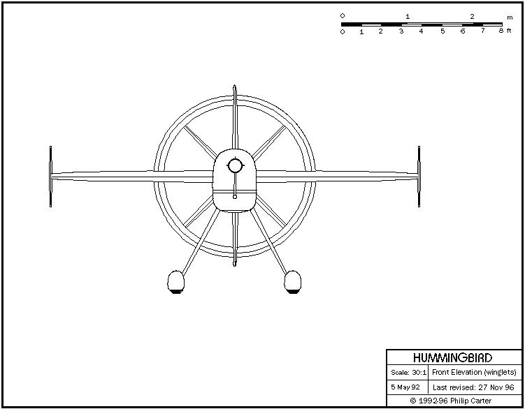
Landing gear and ground clearance issues force a practical limit on duct diameter for the configuration of around 90 inches. Happily this corresponds to adequate thrust levels and an appropriate lateral L/D to fulfill side-flight requirements (so long as the airplane is kept light). In order for the duct to fulfill its lifting-system role with reasonable L/D, duct chord is kept as small as possible while meeting propeller clearance and structural requirements.
The duct is a large and powerful aerodynamic surface which must be integrated with the wing as one lifting system. In particular, to avoid stability and control problems (especially when approaching the stall), and in order for the duct to effectively brace the wing, the duct is positioned longitudinally as close as possible to the wing. Consequently the duct is nested into the trailing edge of the wing as far as is structurally and aerodynamically practical.
Ventral fins brace the upper and lower duct leading edge to the forward fuselage.
Wing
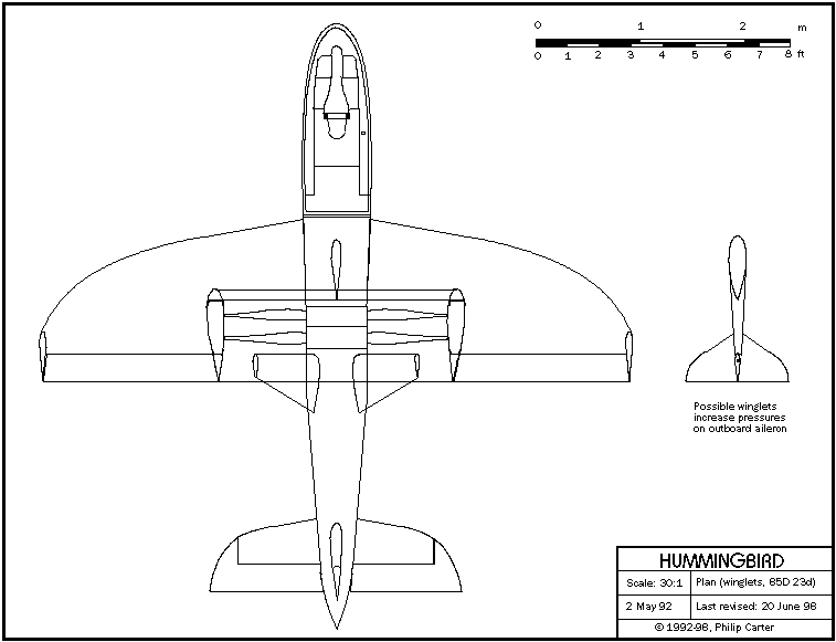
The zero-dihedral wing passes through the horizontal axis of the duct, and the wing trailing edge is recessed 56% of chord adjacent to the duct. At the duct/wing intersection, therefore, we have two airfoil sections, of about 11% and 25% thickness/chord respectively (considered the practical structural and aerodynamic limits of thickness), which must blend together over the forward 20% chord or so of the outboard airfoil. Work has begun on these airfoil sections and efficient candidate sections have been analytically demonstrated.
Ailerons inhabit the wing trailing edge outboard of the duct. While it is not required aerodynamically or structurally that the trailing edges of the duct and outboard wing coincide, it does enhance the visual order and cleanliness of the airplane. Small winglets may be utilized to increase pressures on the outboard aileron and thus increase roll rate.
Engines and Propellers
The propellers are located at their optimum aerodynamic positions relative to the duct while maintaining clearances from each other. The engines are turned 180 degrees to each other and positioned one forward and one aft of the duct.
An early iteration of the design positioned both engines forward of the duct, with one engine modified to counter-rotate, driving propellers through concentric shafts. This led to a CG problem which could not be corrected, since there is little opportunity to alter the relative locations of the major components. Separating the engines fore and aft solves the CG problem at the same time as easing engine packaging and avoiding the need to modify an engine.
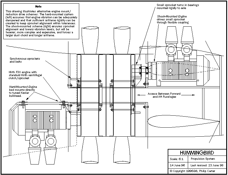
This “mid-engine” configuration presents the immediate problem of routing controls from the cockpit to the tail surfaces. It turns out that the most practical way to bring control pushrods, fuel, engine controls, etc. to the aft engine and tail surfaces is through the rotational axis of the propellers, thus forcing the use of an off-axis reduction drive system such as a cog belt drive. Hirth has available a well-tested, off-the-shelf 3.2:1 synchronous belt drive (Polychain GT) for the F30, the components of which can be adapted to this configuration. The accompanying drawings reflect the geometry of these standard Hirth components.
The propellers rotate on bearings mounted on a large-diameter tubular axle, which is in turn supported at the duct axis by the wing and ventral fins forward, and by stator vanes aft. The axle captures the propellers at the duct axis, facilitating the maintenance of propeller tip clearances under high G loads. Most of the asymmetric gyroscopic forces coming from the propellers cancel in the axle itself, before even reaching the aircraft structure. It will be a simple matter to bring push rods through the propeller axle, providing straight control runs to the tail surfaces.
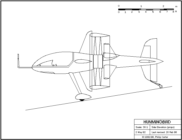
The forward engine is positioned below the propeller axle, the aft engine above. This arrangement prevents cooling air from the forward engine from entering the air inlet of the aft engine, while making both engines easily accessible on the ground for carburetor/injector adjustments while running. It also allows the forward fuselage to be smoothly faired while being lowered slightly from the duct axis, thus shortening the main landing gear and facilitating pilot entry and exit.
Cockpit and Canopy
The pilot is located immediately forward of the front engine and wing leading edge, leaving sufficient space behind the seat for sump tanks, a ballistic parachute, and a small baggage compartment. Since there are no large or heavy components forward of the cockpit, great flexibility is available in the design of seating position, canopy, etc. The pilot can be seated in a semi-reclining position without compromising visibility, and the pilot enclosure can be almost completely transparent, providing helicopter-like visibility. The cockpit floor forward of the seat is a plexiglass window.
The cockpit is clean, uncluttered, and roomy. Primary loads are taken by composite beams running down each side of the cockpit. These beams can be designed to take higher impact loads than would a stressed-skin structure, thus providing the pilot with nose-over protection and some crash protection.
The entire pilot enclosure above the consoles/beams is an unbroken plexiglass molding on a graphite frame. This canopy slides forward for pilot entry/exit and can be quickly removed for maintenance access. In order to effect a reliable seal, the canopy track system lifts the canopy slightly before allowing it to slide forward. While open, the canopy is supported at three points and is not prone to catch the wind; the canopy frame can therefore be much lighter than a hinged canopy. The canopy can remain open during taxi and ground operations, and will keep rain off the panel even while open.
The forward canopy track is a carbon/epoxy tube protruding from the front of the airplane. This tube also mounts the pitot/static ports and angle-of-attack sensors, and a unique forward sighting device for precise pitch and roll reference.
Tail Surfaces
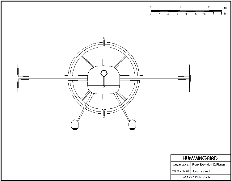
The tail surfaces are of cruciform configuration and positioned centrally in the propeller wash. This arrangement ensures maximum control authority with power at low and zero airspeeds. Conventional hinged control surfaces (fin/rudders, stabilizer/elevators) are employed. The configuration allows the fin and rudder to be located much lower, relative to the CG, than on conventional aircraft, practically negating any adverse rolling moment with rudder and ensuring rudder authority during spin recovery.
Aft Fuselage
Two possibilities present themselves for aft fuselage geometry:
- Twin booms attached to the wing/duct intersections.
- A single boom attached to the stator vanes.
The single boom configuration offers many advantages over the twin boom, including greater stiffness, lower roll inertias, and lower total weight. Since structural stator vanes already exist to support the aft end of the propeller axle and the aft engine, it is natural to attach the aft fuselage at this point as well.
Taking aft fuselage loads through the stators and duct is not so difficult as it may appear, due to the inherent stiffness of the duct geometry and the wide separation of the attach points. The duct is a very efficient structural form which can be designed to carry the required loads without an undue weight penalty. Similarly, it has been determined that correctly designed stators will be quite capable of transferring all required loads from the aft fuselage into the duct. (This is explained further in the section on structures.)
A tapered composite boom of circular cross-section connects the tail surfaces with the stators and mounts the aft engine. Large-diameter propeller hubs (roughly 23 inches) create adequate boom cross-section for structural stiffness and reliable attachment to the stators, with sufficient internal volume to fair the engine and enclose the exhaust system.
The aft fuselage must be removed in order to remove the axle and propellers. This can quickly be achieved through attach points at the stator/duct intersections.
Landing Gear
A taildragger-type landing gear is preferred for several reasons. A tricycle gear would place the mains very close to the duct, leading to aerodynamic interference. Locating a nose wheel on this configuration would be ungainly and would complicate the elegant simplicity of the forward fuselage. The lower fin, and possibly the aft fuselage and stators, will require extra structure to carry the tail wheel loads, but this is still considered a better solution.
The main gear legs angle forward to their attach points. This geometry allows the gear to tie into the seat back bulkhead while minimizing aerodynamic interference with the propellers. The raked gear legs harmonize visually with the lines of the airplane and position a step in the correct location to assist pilot entry and exit.
Two-Place Configuration
The Hummingbird configuration was originally developed as a specialized competition aerobatic machine with a mission to outmaneuver any other human-carrying aircraft. As such, all preliminary development has been centered around a single-place airplane. Early feedback from prospective customers, however, has drawn attention to the need for a 2-place version, both for pilot training and to broaden the aircraft’s appeal as a recreational machine.
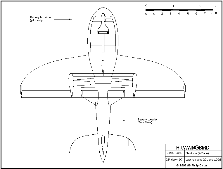
A 2-place version of Hummingbird is complicated by the fact that the pilot CG is situated some 44 inches forward of the aircraft CG, leading to unacceptable CG movement as a passenger is loaded and unloaded. It has been found, however, that if a 2-place side-by-side cockpit is moved aft as far as possible (to the wing leading edge, while moving the BRS to the wider exhaust system bay above the forward engine), the aircraft can be made to balance up nicely by moving batteries around, as in some 2-place helicopters. One 20 lb battery can be located permanently to establish the optimum empty CG, while the other is positioned near the passenger’s rudder pedals if flown pilot-only, and in the aft fuselage if flown two-place. Battery cables will be permanently installed to each location, while quick-release devices will ease the chore of moving a battery as a passenger is loaded or unloaded.
A 2-place Hummingbird will be larger and heavier than the single-place, and will require 150 hp engines to be capable of a hover with two aboard. In general, however, flight characteristics of the two versions will be similar. It is possible that the 2-place aircraft will be built first, due to the wider potential market.


© Copyright 1992-2009 Philip Carter