2D Keel Hydrodynamics
Keel Foil SectionsThe Status Quo
Contemporary IACC keels typically incorporate thin, highly laminar foil sections with a small (roughly 25% chord) plain flap. This is a suitable choice for a single-element system, for the following reasons:
1. A thin laminar section will have minimum drag at low leeway and sideforce (downwind).
2. A thin section, in conjunction with a relatively narrow flap, can tolerate higher flap deflections and leeway angles (and thus higher sideforces) before separation occurs off the low pressure side of the flap - leading to a pronounced drag rise.
The major downside of such sections is the relatively narrow "drag bucket" - meaning that extensive laminar flow (and thus optimum L/D) is available only through a very limited range of leeways and flap (trim tab) deflections.
Why Multi-Element Foils?
Fluids do not like going around sharp corners. A deflected plain flap generates such a corner; a multi-element flap does not. Further, multiple elements work together to generate lift coefficients beyond that possible for a single element.There is a downside, of course: a multi-element foil system cannot match the minimum downwind drag coefficients possible with a single thin foil, largely because structural constraints force a thicker keel strut, and because the multiple foils are operating at lower Reynolds numbers. As we shall see, however, there are ways around this problem.
Sailors are very familiar with multi-element foils, since every decent sailboat has one - the foresail and mainsail together constitute such a system. Dennis Connor's 1988 catamaran sported a rigid multi-element rig to good advantage. So, what I am proposing here is not new - except that it is under the water.
2D Foil Analysis Notes
The foil section designs and analyses described here have been performed with the aid of two special-purpose CFD programs written by Mark Drela of MIT:
XFOIL - for single element foil section design/analysis
MSES - for multi-element foil section analysis
These codes are unique in their ability to capture the physics of the boundary layer, and thus to accurately predict laminar transition, which has a significant bearing on resultant lift and drag coefficients. Consequently, 2D performance data generated by these codes are typically more accurate than predictions from general purpose 3D Navier-Stokes codes such as Fluent, which have limited transition models.
All foil analyses were performed at Reynolds numbers scaled to the chord length of the target application, based on a factor of 4.21e6/meter (corresponding to slightly less than 10 knots in sea water).
MSES analyses show a Mach number of 0.01 simply because the code's formulation does not accept a zero Mach number. The number is sufficiently low to have an insignificant influence on results.
The parameter "Ncrit" relates to freestream turbulence levels, and is set at 12 for all cases. This value presumes a relatively low water freestream turbulence level.
Both XFOIL and MSES are validated codes. For expedience sake, single-element cases have been analysed in XFOIL, multi-element cases in MSES. Comparative testing of the two codes over a range of single-element cases showed results to match closely, typically within 1%.
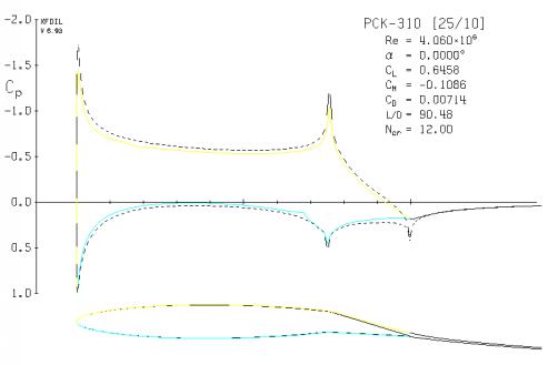
Reference Foil Section (PCK310)
To provide a reference point for this study, results are compared with those of a conventional keel foil section optimized for downwind performance.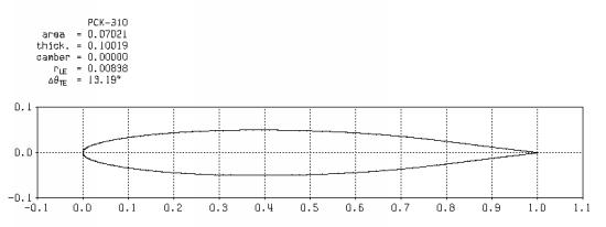
Our reference keel assumes a 25% chord plain flap and a chord length of 0.965 meters.
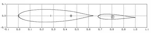
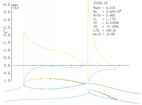
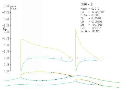
Candidate Multi-Element Foil (CK09)
Downwind Foil Performance
The excellent downwind performance of the PCK310 makes it tough for any multi-element system to match at this point of sail. We begin by looking at the PCK310 with zero tab deflection and zero leeway, with the boundary layer tripped at the flap juncture (73% chord).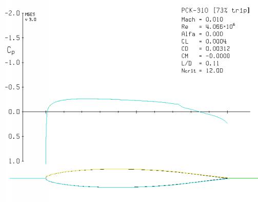
Notice, however, that the CK09's Reynolds number is substantially lower, since it is designed for a chord length of 0.813 meters, yielding a surface area just 84% that of the single element keel. The minimum keel blade profile drag for the multi-element foil therefore turns out to be just 11.2% higher than that of the single-element PCK310.
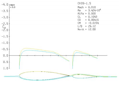
Multi-element foils can be optimized further for downwind performance, as is demonstrated by the MEK01 foil at a still lower Reynolds number, corresponding to a chord length of just 0.77 meters.
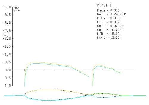
Minimum Flap Deflection
The CK09 is analysed at a flap deflection of 1.5 degrees in order to prevent the keel strut wake from tripping the flap boundary layer. If the boundary layer is tripped on one side of the flap, MSES predicts a profile drag increase of about 18% - definitely something to be avoided. Due to its smaller flap, the MEK01 can tolerate a flap deflection as low as 1 degree without tripping the flap boundary layer. The minimum flap deflection can be reduced by reducing flap chord or increasing foil separation, the penalty being a reduction in maximum lift coefficients.Since IACC yachts don't run directly downwind, there will always be some sideforce, and if (as is my understanding) the trim tab is not applied downwind, the boat will make some leeway, and the drag figures predicted here for the single-element section will be artificially low - even before considering the additional hull resistance.
The 1.5 degree flap deflection of the CK09 multi-element section generates a lift coefficient of about 0.1 at zero leeway. This leads us to the question: Can IACC yachts utilize the corresponding sideforce when sailing downwind? The optimum sailing angle downwind will likely be higher than for standard keels, since this sideforce is generated extremely efficiently.
Flap Juncture Drag
Also not considered in these analyses is the additional drag created by the strut/flap juncture of the single-element foil, which runs the full length of both sides of the keel. Even with the best fairing schemes, the subsequent drag hit will be significant compared to the very low drag of the parent foil.By contrast, the multi-element foil has no such spanwise surface aberrations. The drag contribution of its hinge arms, faired back in the downwind configuration, will be significantly less than that of the single-element foil's spanwise flap juncture. It is possible that this fact alone could be enough to wipe out the single-element foil's downwind drag advantage.
Downwind Maneuvering
The PCK310 retains its superb downwind performance only within about +/- 1 degree leeway. Gybe maneuvers will take the foil out of its low drag region, after which the multi-element foil pulls away. The net result is lower energy losses for the multi-element keel through downwind maneuvers.
Upwind Foil Performance
Now we consider the keel's most fundamental task - generating efficient sideforce while sailing upwind. Since our goal is to minimize hull resistance by sailing at zero leeway, we begin by looking at the two foils near their maximum lift capability (the PCK310 with 16 degrees flap, the CK09 with 18 degrees flap) at zero angle of attack.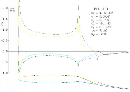
Just as important, the CK09 multi-element foil achieves this with a lift/drag ratio (L/D) 48% higher than that of the PCK310.
To be fair, we will look at the condition where the single-element foil is most efficient - at about 10 degrees flap deflection - and compare it to the CK09 with 12 degrees flap, with both foils at zero leeway.
The multi-element foil excels also at higher leeway angles, as will be seen later when we analyse the candidate keels over their entire operating range.