Duct Myths, Duct Physics
Duct Physics Without Numbers
Duct Myths
Widespread disagreement prevails about the properties of ducted fans—or shrouded propellers as they are sometimes called. In general, the term ducted fan is applied to configurations of small disk area, high rpm, and low aspect ratio (long, narrow ducts), while a shrouded propeller has larger diameter, lower disk loading, lower rpm, and a high aspect ratio (short chord) duct. Many varieties of ducts and shrouds are possible, each with its own characteristics, which explains the conflicting opinions and evidence regarding their efficacy.
First, let us dispel a couple of myths:
Myth 1: A ducted fan is less efficient than a free propeller.
This is a meaningless statement, since it does nothing to compare apples with apples. Whether ducted or free, the basic rule is that a propeller with low disk loading (thrust or power vs. disk area) will be more efficient that one with high disk loading. Small diameter, high disk loading ducted fans are often conceived to allow the use of a high rpm engine running a direct drive propeller. While these highly loaded fans (if properly designed) will be more efficient than a free propeller of the same diameter, they typically won’t match the efficiency of a larger free propeller (of much lower disk loading), leading to the myth that ducted fans are “less efficient.”
It has been amply demonstrated, both theoretically and empirically, that a ducted fan (shrouded propeller) system, properly designed for a specific operating condition, will always outperform (propulsively) a free propeller of the same diameter (that is, it will produce more thrust for the same power input) at that operating condition. While this fact is always true (at least at subsonic speeds), it neglects the drag of the duct itself, which at high speeds can easily overcome propulsive benefits.
Myth 2: Ducted fans are efficient only at high speeds (where turbofans operate efficiently).
In fact the opposite is true. As speeds increase, high mass flow becomes easier to attain as a result of the speed itself, making large disk-areas (and ducts) less important or effective. At the same time, however, duct drag rises with the square of the speed.
Why then do turbofan engines always place the compressor in a duct? For a very different reason: to slow the airflow so that the compressor can operate subsonically even when the aircraft is close to sonic speeds—or even supersonic! The compressor duct of a turbofan engine actually lowers the propulsive efficiency of the compressor (slows the airstream) in order to avoid a transonic drag rise.
The UDF (unducted fan) seeks to avoid this tradeoff by doing away with the duct altogether and designing the compressor (propeller) with exotic planforms and airfoils to operate efficiently in the transonic realm. This approach has its own problems, of course, and the ducted, high-bypass turbofan is still the most efficient high-speed engine we have.
Duct Physics Without Numbers
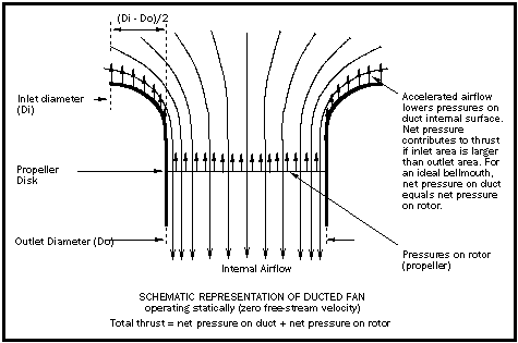
We begin by looking at a ducted fan operating statically (zero free-stream velocity or airspeed).

According to this simplified approach, for a ducted fan system operating statically, net pressures on the duct inner surface will contribute to thrust if the inlet area is larger than the outlet area (called positive camber). In reality, it has been shown that even a zero-camber duct can contribute to thrust, due to the complex 3-dimensional flow around and through the duct.
For a given propeller there is an ideal duct shape (bell mouth) which will optimize the duct’s contribution to static thrust. The magnitude of this contribution from the duct can be significant; a theoretical result (from Theodorsen’s Theory of Propellers) states that the thrust of a ducted fan with an ideal bell mouth will be equally divided between pressures on the rotor and pressures on the duct!
A further important factor is "diffuser ratio", being the ratio of exit_area/disk_area. Theoretically, static thrust increases with diffuser ratio: as the induced airflow is slowed by the expanding duct aft of the propeller disk, pressures increase on the inner duct wall, thus contributing to thrust. In practice, diffuser ratio is strictly limited by the requirement to avoid separation.
In summary, ducted fans can produce more thrust than a free propeller of the same diameter for the following reasons:
- The duct extends the reach of the propulsion system radially to work on a larger mass of air (by analogy, a “non-planar” propulsion system) and thus the system takes on the characteristics of a free propeller of larger diameter.
- If clearances between the propeller tips and duct wall are kept small compared to tip chord, the presence of the duct wall will maintain pressures on the blade towards the tip, improving blade L/D.
Since the total thrust of a ducted fan/shrouded propeller is the sum of pressures on the propeller and pressures on the duct, to increase thrust one increases the net propulsive pressures on the duct and/or on the propeller. To increase net pressures on the propeller for a given power input, one increases the blade L/D by keeping tip clearances small. To increase net pressures on the duct, one optimizes the duct geometry for a specific airspeed.
For more on Ducted Fan theory, see the Links Page.
Hummingbird’s Duct Design
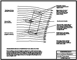
We now have the propulsive basis for Hummingbird’s duct design. At the same time, of course, we must design the duct to function efficiently as an annular wing.
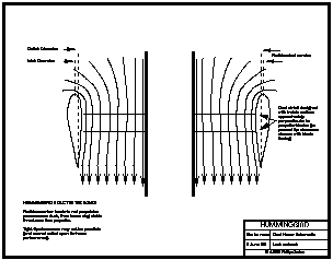
Because of Hummingbird’s very high power/weight ratio and counter-rotating propllers, it is not necessary that the duct be heavily optimized for static thrust. In fact, we would have sufficient thrust to hover (at sea level, at least) even if the duct contributes nothing whatsoever propulsively. This gives us tremendous flexibility in designing the duct for the ideal L/D and stall characteristics. Thrust augmentation is free lunch.
Perhaps the most important requirement is to avoid separation at the duct inlet under high power static conditions. This forces a large leading edge radius, which also contributes to the duct's ability to generate high lift coefficents.
Tip clearances will be higher than propulsive optimums, for the following reasons:
- Structural requirements are greatly eased (to avoid blade/duct contact).
- Duct surface velocities are reduced under static conditions, allowing a duct inlet geometry optimized for L/D while avoiding inlet separation.
It turns out that a small amount of positive duct camber (inlet area larger than outlet area) is beneficial for both propulsion and flight. The optimum duct camber, along with the optimum duct airfoil, are two of the most important parameters influencing Hummingbird’s aerodynamic design.


© Copyright 1992-2009 Philip Carter
