Propulsion System Details
Reduction Drive
Engine Mounting
Engine Cooling
Fuel System
Propeller Axle
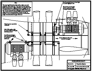
The axle is a simple metal alloy tube of about 4 inches ID, with some machining on the outer surface to facilitate the installation of bearings and attach structures. The propeller axle greatly simplifies and lightens propeller hubs and bearings while providing access between the forward and aft fuselages. It is mounted to the airframe at each end through flexible attachments, thus preventing concentrated stresses through relative movement of the forward and aft fuselages.
The propeller axle will likely be manufactured from titanium alloy to address thermal expansion and fatigue concerns.
Reduction Drive
The standard Hirth 3.2:1 Behlen (62 mm PolyChain GT) belt drive provides the correct geometry for this configuration, allowing the use of Hirth’s standard small sprocket and centrifugal clutch. This standard geometry provides an appropriate propeller RPM and displaces the engine the correct distance from the centerline, permitting straight control runs through the axle. Shafts are done away with by attaching the large sprocket directly to the propeller hub.
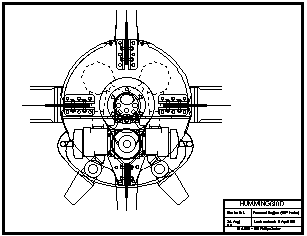
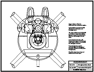
It should be noted that using larger sprockets or gear ratios would force the use of longer belts, which would displace the engines further from the centerline, complicating the structural interference between the aft engine and upper stators, and the forward engine and lower ventral fin. This will not be an issue if Wankel engines are used.
If, as is likely, higher-powered engines are used, it should be possible to retain the 62 mm belt width while upgrading to a new generation of synchronous belts which promise a 50% improvement in power density over PolyChain GT. This is an important consideration, since wider belts would probably force an increase in duct chord.
Engine Mounting
If the engines are to be shock mounted, some scheme will need to be devised to maintain belt tension. Considering the loads to which the airplane will be subjected, one could expect significantly less complexity and weight, along with greater reliability, if the engines can be hard mounted. The Hirth engines are much lighter, of less cubic capacity, and higher reving than conventional engines, so it may be possible to sufficiently dampen engine vibration through the clever design of rigid engine mounts, perhaps making use of the dampening properties of Kevlar structures. Vibration won't be an issue if Wankel engines are used.
If sprocket alignment proves difficult to hold within limits, the fix will be to mount the small sprocket directly to the axle and drive it through a flexible coupling. This arrangement would allow the engines to be shock mounted, but will be avoided if possible since it would add length and weight to the aircraft.
Engine Cooling
The aft engine and exhaust system will receive reliable cooling air from the propeller blast, while the front engine may require fan cooling—particularly while in the hover. There is a blower available from Hirth for an 8.5 lb weight penalty, but it interferes with the sump tanks and does not fit well into the Hummingbird installation. Cooling air for the forward engine enters above the wing (thus cooling the exhaust system first), and then passes through large openings in the engine mount bulkhead and through the baffled cooling fins, exiting immediately forward of the propellers.
When the aircraft is stationary on the ground after engine shut-down, heated air from both engines will be free to convect forwards and upwards out of the air inlets.
Cooling air-cooled Hirths in this application may be sufficiently problematic to justify using the forthcoming liquid-cooled engines. Liquid cooling will provide greater flexibility in the cooling system installation, and would better accommodate Hummingbird’s widely varying airspeeds and power settings while avoiding overheating or shock-cooling.
Fuel System
Attention has been given to designing a fuel system which is simple and reliable, and which optimizes aerobatic performance while providing sufficient cruise endurance.
Two sump tanks (one for each engine) of approximately 4 US gallons each are located immediately forward of the front engine. This places the 48 lb of sump fuel about 11 inches forward of the CG, so the loaded CG moves aft about 0.6 inches as sump fuel is burnt off. Each sump tank contains fuel pickup and pump systems to ensure reliable fuel delivery to one engine at any attitude and acceleration, and will keep that engine running at full power for about 20 minutes (the F30 burns about 10 USgal/hr at full throttle). Since the sump tanks are independent of each other, a fuel system contamination or failure will affect only one engine. A cockpit-controllable crossfeed system will allow one sump tank to drain into the other in the case of an engine shutdown.
Secondary tanks of about 12 gal per side are built into the wings inboard of the duct intersections. These tanks are about 8 inches forward of the CG; full fuel will therefore move the CG forward about 1.6 inches from the unfueled condition, leading to a more stable aircraft when ferry fuel is on board.
An appropriate cruise configuration might see each F30 engine burning about 5 gal/hr while producing 50 hp. The total fuel quantity of about 30 gallons would then provide an absolute endurance of about 3 hours. Further endurance and range could be realized by shutting down one engine, feathering the prop, and cruising on one engine while cross-feeding fuel.
The low location of the sump tanks allows the wing tanks to gravity-feed freely into the sumps at positive G. Check valves prevent fuel flowing from sumps to wing tanks under negative G. Competition aerobatics would normally be flown with full sump tanks after using the wing tanks to get the aircraft into position.


© Copyright 1992-2009 Philip Carter


