
SPORT AEROBATICS Article
The following article was commissioned by Sport Aerobatics magazine - the official publication of the International Aerobatic Club - and was first published as the cover story of the August 2001 issue.
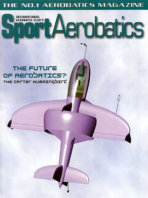
The Future of Aerobatics?
The Carter Hummingbirdby Philip Carter
 You are on the runway at air show center, engines idling. When the cue comes, you take a deep breath and advance the throttles to full power. Instantly you are thrown forward at some 1.4 Gs, straight down the centerline.
Within three seconds you are airborne, accelerating rapidly as you rotate into a vertical climb. You ease back on the throttles and listen for the variometer indicating zero climb at about 200 feet. With airspeed pegged at zero you nimbly roll to the left, feed in some rudder, and translate horizontally back down the runway. Directly over your takeoff point you bring the airplane to a stop and wave to the crowd. A “curtsy” with a wag of your tail signals the beginning of your performance.
Back to full power to demonstrate your vertical mobility, and the aircraft accelerates out of the hover on the vertical line. You throw in some rolls and snaps as you ascend, admiring the view through the expanse of Plexiglas as thousands of eyes gaze back in disbelief.
As you approach 5,000 feet, your helicopter airspeed indicator indicates that your engines and propellers are running short of air, so you push over the top and head back down while pulling back the throttles and punching the DRAG buttons on the propeller controller. Turbulent air from the propellers sends a buffet through your side stick and pedals as your airspeed stabilizes at about 180 knots on the vertical downline. Following some 15 seconds in a vertical dive, you reset the propellers and feed in rudder to pull out on the knife-edge. To drive home your knife-edge capability, you continue on around in a tight knife-edge loop.
It is time for your hover routine, but first you decide to produce some magic during the transition. You roll onto your wing and deftly manage the throttles to slow the airplane down, taking care to stay coordinated as the outboard wings cleanly stall. As you pitch up and apply power, the aircraft enters into post-stall slow flight, levitated by the propeller wash passing over the inboard lifting system. At some 15 knots you demonstrate complete control by rolling through 360 degrees.
After the piloting challenges of the “powered lift” regime, pitching up into the hover comes as something of a relief. You demonstrate control in the hover by pitching and yawing, translating horizontally on each axis, combining rolls right and left. Then you apply full power and full rudder to somersault the aircraft through 360 degrees, losing some altitude in the process. You climb vertically back to a safe altitude and follow with a somersault on the pitch axis, and (if you are good enough) throw in a roll for good measure.
To prove that you are flying a serious aerobatic machine, you complete your performance with a conventional aerobatic routine incorporating inside and outside loops, spins, and snaps. The aircraft flies the sequence as well as any other, with a few significant differences: The aircraft behaves identically right and left and identically through inside and outside maneuvers; and the entire sequence is flown at lower speeds, closer to your audience.
While this may appear to be the fanciful flight of dreams, you may be surprised to learn that such capabilities can be accomplished with known technology, relying on nothing more than internal combustion engines and aerodynamic interaction with the atmosphere. Turbines, rockets, and reaction jets are not required. The secret lies in an original aircraft configuration, developed from the ground up to fulfill the aerobatic mission. I call this new class of aircraft “The Hummingbird Configuration.”
The Generalized Aerobatic Mission
The practicing aerobatic pilot may ask, “What is the use of such capabilities when they don’t exist in the aerobatic catalog?” The answer is that the FAI Aerobatic Catalogue generally reflects the capabilities of existing aircraft, rather than the pure ideals of aerobatic flight. This is demonstrated, for instance, by the fact that knife-edge maneuvers were removed from the catalog in 1987 on the premise that they were never used in competition since current aircraft are simply not capable of flying them to a sufficient standard.
It is instructive, therefore, to attempt to define idealized aerobatic flight without regard to present or perceived technical limitations. I will begin by proposing such a definition for what I call “The Generalized Aerobatic Mission.”
In its most generalized form, aerobatics could be defined as:
The precise control of attitude and velocity on three axes in three-dimensional space, relying solely on inertias and aerodynamic interaction with the atmosphere.
We could further qualify this generalized definition as follows:
- Since this definition specifies only inertial and aerodynamic forces (aerobatics), reaction-type propulsion or control systems are not permitted.
- To satisfy competition requirements, and to focus the mission as a performing art, we define “three-dimensional space” as a kilometer cube (the aerobatic box).
- Control of velocity is more important than maximum velocity. Maximum airspeeds need not be greater than that required to pull 10 to 12 Gs (human bodily limitations). In practice, high speeds are of little use in the aerobatic box—particularly if the aircraft can climb vertically without relying on stored energy (kinetic energy, or speed).
- Since the control of airspeed is more important than maximum airspeed, a lower wing loading allows aerobatic figures to be performed at lower speeds with reduced G-forces, or with similar G-forces in a smaller airspace, more visible and accessible for judges and spectators.
- An aerobatic aircraft should be able to fly the complete FAI Aerobatic Catalogue as a subset of its flight envelope.
Further developing the Generalized Aerobatic Mission, we note that the “precise control of attitude and velocity” facilitates three key (and intuitively desirable) aerobatic qualities: maneuverability, mobility, and symmetry.
Maneuverability: The ability to change attitude and direction on three axes. This involves the generation of forces and moments on each axis. Maneuverability should ideally be decoupled from velocity, meaning that a perfectly maneuverable aircraft would retain the ability to change attitude and direction at zero airspeed, and even at negative airspeeds. This also implies the ability to fly at zero airspeed (hover) while maintaining full three-axis control.
Mobility: The ability to move from any location directly to any other location (within the aerobatic box). Mobility is an extension of maneuverability. It follows that a fully mobile airplane will be capable of flying a sustained line straight up and straight down.
Symmetry: For every maneuver there is a geometrically opposite maneuver.
The Goal of Symmetry
The ideal aerobatic aircraft would demonstrate symmetrical flight characteristics on each axis. Modern aircraft are designed to perform similarly through inside and outside maneuvers. Such “vertical symmetry” is but one of several possible symmetries.
In practice, some asymmetries are unavoidable. An optimized aerodynamic device will always favor a particular direction of motion, for instance, and gravity is always pointing straight down. Nevertheless, symmetry remains a fundamental goal inherent to the aerobatic paradigm. Following are some key symmetries encompassed by the Generalized Aerobatic Mission:
Vertical Symmetry (positive/negative G; inside/outside maneuvers)
This is demonstrated by most modern aerobatic aircraft, with symmetrical wing sections and sometimes 0, 0, 0 rigging (0-degree wing incidence, tail incidence, and dihedral). Current aircraft do very well in this regard.
Lateral Symmetry (left-handed/right-handed maneuvers)
Modern aerobatic figures emphasize the equality of left-handed and right-handed maneuvers—rolls, spins, snaps, and so on. The natural lateral aerodynamic symmetry of a bird and most aircraft yields symmetrical flight characteristics left and right—when flown power off. A single engine and propeller destroys this natural symmetry (see Propulsive Symmetry below).
Vertical/Lateral Symmetry (side-flight; knife-edge maneuvers)
Vertical/lateral symmetry ideally requires that any maneuver flown upright or inverted should also be flyable laterally—on the knife-edge. It follows that aerodynamically demanding maneuvers (such as loops) should be flyable in side-flight (knife-edge). In practice, this will likely remain a qualitative symmetry, since practical dimensional constraints (such as ground clearance and landing gear length) limit vertical span, thus ensuring that attainable lateral aerodynamic performance will fall short of upright and inverted aerodynamic performance.
Longitudinal Symmetry (forward/backward flight; thrust/drag)
Ideally, longitudinal symmetry would require the equivalence of available thrust and drag forces, at any airspeed, and the ability to fly backward on par with forward flight. Clearly, this is not possible with known aerodynamic technology. As with lateral aerodynamics, therefore, the goal is to achieve a qualitative symmetry, which implies the ability to generate and control significant drag forces as well as thrust forces and the ability to fly backward at some low but significant (negative) airspeed under full control.
Propulsive Symmetry
As mentioned above, current aerobatic aircraft are propulsively asymmetrical due to the single rotating engine and propeller, which create torque moments and a rotating propeller wash. Consequently, current aircraft behave differently to the left than to the right, requiring differing pilot technique through left- or right-handed rolls, spins, snaps, etc. Further, propulsive asymmetry renders a fully controlled hover impractical, even if sufficient thrust is available.
Propulsive asymmetry does provide the gyroscopic forces required to complete some tumbling maneuvers. (The use of inertial forces is permitted under our generalized definition.) Nevertheless, the symmetry principle demands the ability to perform the mirror image maneuver, which is not possible with a single engine and propeller.
An ideal aerobatic aircraft would provide propulsive symmetry, thus yielding true equivalence between left- and right-handed maneuvers, while also providing the choice of propulsive asymmetry (in either direction) when the need arises to complete gyroscopic maneuvers.
Aircraft Specifications
Having defined our Generalized Aerobatic Mission, and having expanded it to embrace the ideas of maneuverability, mobility, and symmetry, we are now in a position to more precisely define our ideal aerobatic aircraft.
Maneuvering Rates
The aircraft should exhibit maneuvering rates equal to or better than current aircraft in roll, pitch, and yaw. Furthermore, to satisfy our maneuverability requirements, positive control authority on all axes must remain available at zero airspeed and at low (but significant) negative airspeeds.
Accelerations
On the vertical axis (inside/outside maneuvers), the aircraft must be capable of generating accelerations exceeding human bodily limitations, equating to 10 to 12 Gs positive/negative. (This is achieved by current aircraft.)
On the lateral axis (knife-edge maneuvers), the aircraft must be capable of generating sufficient accelerations to fly knife-edge loops, tending toward square loops. This translates to about 5 Gs lateral acceleration, or 50 percent of available vertical accelerations.
On the longitudinal axis (thrust/drag), our mobility goals require that the aircraft be capable of generating accelerations better than 1 G, both forward and aft, equating to available thrust and drag forces greater than aircraft weight. In practice, available drag forces at low airspeeds will be substantially less than thrust forces, whereas at high airspeeds, available drag forces will be greater than thrust forces. A sustained vertical climb requires that a net 1 G thrust force remains available at some significant forward airspeed, while a sustained vertical dive requires a 1 G drag force to be attainable at some airspeed less than the never-exceed speed.
Speeds
No specification is given for maximum airspeed. It is sufficient to reiterate the following:
- Control of airspeed is more important than maximum airspeed.
- An aircraft with sufficient thrust-to-weight ratio will not require high airspeeds to achieve vertical mobility.
- An ideal aerobatic aircraft will demonstrate controlled flight throughout the range between its maximum airspeed and some significant negative airspeed.
- Lower airspeeds are to be favored through a given aerobatic sequence, since G-forces are reduced and/or the sequence can be flown within a smaller airspace.
Propulsive Symmetry
The aircraft should be propulsively symmetrical, thus restoring lateral symmetry under power. Propulsive symmetry also permits a balanced hover with full three-axis control. The pilot should retain optimal control through the option of establishing propulsive asymmetry, in either direction, to facilitate both left-handed and right-handed gyroscopic maneuvers.
Ergonomics
The pilot is the eyes and brain of the machine and therefore must be afforded optimal visibility and attitude reference while enduring minimum workload. Further, the pilot should ideally be situated forward of the aircraft center of gravity, where local accelerations resulting from attitude changes correctly anticipate subsequent aircraft accelerations. Reclined seating should be employed to increase G tolerance.
The Hummingbird Configuration
First, however, we could ask the question: “Why a new configuration? Have not the standard biplanes and monoplanes stood the test of time?” Indeed they have. Conversely, could it not be suggested that it was an extraordinary coincidence, or a great stroke of genius, that the early designers came up with the optimum configurations for aerobatic flight within 10 years of the birth of powered flight? Especially considering that these configurations were not devised specifically for aerobatics?
In all fairness, it must be noted that past and present designers have done an extraordinary job of bringing the classic configurations to an extreme state of refinement. The indications are, however, that the limits are being approached. Two such limits are lateral aerodynamics and thrust-to-weight ratios.
It can be shown that, as thrust-to-weight ratio is increased, so must the ratio of propeller blade area to aircraft weight and wing area. Placed far forward on conventional configurations, the large blade areas begin to seriously degrade pitch and yaw stability, while generating high gyroscopic forces and torque asymmetries. I contend, therefore, that any conventionally configured aircraft capable of a sustained vertical climb will encounter serious handling compromises, including a tendency to enter flat spins. Further, the forward propeller location limits its use as a drag brake and precludes significant coupling of the propulsion system with the lifting system and control system.
The lateral lift of conventional configurations is limited by the lack of vertical surface area. A vertical planar wing sufficient to meet our knife-edge objectives would require at least 12 feet of vertical span and would pass directly forward of (or through) the cockpit—a ghastly beast, to say the least. It is not difficult to understand, therefore, why knife-edge maneuvers were removed from the FAI Aerobatic Catalogue.
Further compromises implicit in the classic configurations are the high pitch and yaw inertias resulting from the forward-mounted engine and propeller, and visibility is inevitably restricted by the engine and wings.
So we are forced to set aside the classic configurations, simply because they cannot be massaged to fulfill our Generalized Aerobatic Mission. Instead, we start with a clean sheet of paper and address our challenging specification from fundamental principles.
Non-Planar Wings
Aerobatic aircraft are faced with the aerodynamic challenge of generating high lift forces while limiting airspeeds (to stay in the box) and wingspan (to minimize weight and maximize roll performance). The problem is lift-induced drag, which becomes increasingly dominant as speed and span are reduced. The modern monoplanes (with planar wings) deal with this by increasing wing loading and flying faster through aerobatic routines, thus subjecting pilots to extreme G forces. Non-planar wings have long been known to reduce induced drag while limiting wingspan. This explains why aerobatics remains the last bastion of the biplane—the biplane being the most common class of non-planar lifting system. Biplanes also take advantage of the vertical separation of the lifting surfaces to implement efficient structural bracing, with the cost of high parasite drag.
The Annular Wing
Having noted the desirable properties of non-planar wings, we proceed to ask, “Is there an alternative non-planar lifting system providing the benefits of the biplane, but without the parasite drag?” We come to the most fundamental (and contentious) feature of our new configuration: The annular wing, sometimes called a “ring wing.”
Annular wings have been a curiosity of the aeronautical world for many years. Long studied in academic circles and well tested and proven in numerous model aircraft, they have never found their place in manned flight—until now.
Like any other wing, annular wings generate both lift and profile drag. In addition, they exhibit two unique aerodynamic properties of great value to aerobatic flight:
1. An axisymmetric annular wing performs identically at any angle of bank.
2. An annular wing produces just half the induced drag of a conventional (planar) wing of the same span generating the same lift.
Clearly, an annular wing works its magic equally well in upright, inverted, or knife-edge flight. In fact, the annular wing’s high span efficiency yields sufficiently powerful and efficient lateral aerodynamics to meet our knife-edge objectives, while limiting vertical span to practical dimensions. Further, like the biplane, the annular wing’s vertical extension provides the opportunity for efficient structural bracing, but with a reduced drag cost.
The Hummingbird Lifting System
Since our mission demands vertical (upright/inverted) aerodynamics roughly twice as powerful as the lateral aerodynamics, we add a horizontal planar wing through the axis of the annular wing. This forms the basis of Hummingbird’s lifting system.
The planar wing and annular wing form a single, integrated lifting system. Longitudinally distributed lifting systems (canards, tandem wings, etc.) are unsuitable for aerobatic flight because of unpredictable stall behavior (if they will stall at all). For an aircraft that must routinely and predictably stall, snap, and spin, this is clearly unacceptable.
For this reason, Hummingbird’s annular wing is nested into the trailing edge of the planar wing as far as is structurally and aerodynamically practical. Furthermore, the planar wing is swept to bring its aerodynamic center closer to that of the annular wing. Thus, stall development over these uniquely different surfaces will not significantly affect trim or degrade stability.
The lifting system is completed by ventral fins (which also provide structural load paths) and small winglets, designed to further improve overall span efficiency and rolling moments. Each of these vertical surfaces contributes to the lateral lifting system, assisting the annular wing in knife-edge flight.
The curvaceous wing planform is driven by aerodynamic factors. While a double-taper planform could be devised to produce a similar result, leading edge separation would occur at the taper-break at lateral angles of attack. The wing trailing edge has zero sweep and coincides with the annular wing trailing edge, partly because it yields optimized planforms and partly to produce clean geometric lines.
The Annular Wing as a Duct
Fortuitously, it turns out that an annular wing sized to meet our lateral aerodynamics (knife-edge) objectives coincides with a propeller diameter meeting our thrust objectives. Thus, our annular wing does double duty as a propeller shroud, or duct, with the associated gains in static and low-speed thrust.
Here lies hidden gold. Since our annular wing is simultaneously a powerful lifting surface and a propulsor duct, we have succeeded in aerodynamically coupling the lifting system with the propulsion system. In essence, if the aircraft is moving very slowly through the air, then controlled flight requires us to blow air over (or through) the aircraft’s lifting surfaces. In one stroke, our slow flight objectives become attainable.
Despite first impressions, the primary function of Hummingbird’s duct is not to augment thrust. In fact, the machine has sufficient power-to-weight and propulsive efficiency to hover without a duct at all. Consequently, tight propeller tip clearances are not required, which greatly eases structural constraints, while simultaneously easing the implicit compromises in duct/annular wing airfoil geometry. The primary purpose of Hummingbird’s “duct” is to generate efficient aerodynamic lift at all roll attitudes. Its second aerodynamic function is to couple the lifting system with the propulsion system. Thrust augmentation is free lunch.
Propulsion System
Our propulsive symmetry/asymmetry goals can be achieved by implementing independently powered, counter-rotating, coaxial propellers. Counter-rotating coaxial propellers can also provide a minimum-energy (non-rotating) wake and thus optimal propulsive efficiency, particularly at low and zero airspeeds. Analytical studies predict that such a system can produce 3 to 5 percent more static thrust than a single propeller of the same diameter absorbing the same total power.
The propellers are placed at their optimum locations relative to the duct. Center of gravity issues are addressed by placing one engine immediately forward of the propellers, the other aft. The engines and propellers are thus located near the aircraft CG, reducing pitch and yaw inertias over standard configurations. The propellers rotate on a fixed tubular axle, which is supported between the forward and aft fuselages. Simple synchronous belt or gear transmissions complete the power trains, with no need for shafts.
The propellers turn at low rpm, for several reasons: Tip speeds are kept below the transonic realm, gyroscopic inertias and centrifugal forces are reduced, and blade areas are increased. The wide-chord blades offer greater stiffness for their weight, while providing a powerful drag brake (with the appropriate blade pitch control) sufficient to meet our vertical mobility objectives.
Hummingbird’s design criteria demand engines of high power-to-weight ratio and compact size, preferably liquid cooled. Our performance goals can be met with modern generations of two-stroke and Wankel engines of approximately 150 hp each. The completely independent engine/transmission/propeller/electrical systems offer redundancy unavailable with any other aerobatic aircraft.
Structural System
The duct/annular wing forms the heart of Hummingbird’s structural system. The cockpit pod (forward fuselage) extends forward of the wing, as desired, and attaches to the duct through the inboard wings and ventral fins. The aft fuselage boom, supporting a cruciform empennage, is attached to the duct through four “stators,” each oriented at 45 degrees relative to the wings and ventral fins. The duct is thus braced at eight points around its circumference, forming an extremely rigid offset octagonal truss that limits duct distortion and braces the wings against bending and torsion.
It should be emphasized that fuselage loads go through the duct, not through the propellers. In fact, the propellers and axle could be removed without affecting the aircraft’s structural integrity.
Control System
Since the rudders and elevators are located immediately aft of the duct and centrally in the propeller wash, pitch and yaw control are maintained (power on) at zero airspeed and even at low negative airspeeds. Positive rudder control is assured during spin recovery by placing almost half of the fin/rudder area below the horizontal stabilizer.
Conventional ailerons inhabit the planar wings outboard of the annular wing. In addition, small control surfaces (“statorons”) are located on the stators, assisting the ailerons during forward flight while providing roll control (power on) at zero and negative airspeeds. In other words, simply by adding small control surfaces to the stators, and with no further changes to the control system, the configuration yields a powerful three-axis vectored thrust system.
Control linkages pass from the cockpit to the statorons and tail surfaces through the tubular propeller axle, as do the aft engine controls, fuel lines, and wiring. In concert with the symmetrical (torque-free) propulsion system, three-axis control is maintained throughout the specified flight envelope.
SKY DANCING: A Fresh Aerobatic Paradigm
It is hoped that this brief synopsis will impress you with the elegant physics underlying the configuration, resulting from the simultaneous optimization and integration of the lifting system, propulsion system, structural system, and control system. For these reasons, along with the advanced ergonomics, I propose the Hummingbird configuration to be the optimum solution for the Generalized Aerobatic Mission.
Hummingbird is not intended to compete directly with the classic configurations. It is a fresh class of aircraft, one of a handful of unique configurations developed since the dawn of manned flight, expressly developed to maneuver freely and precisely in three-dimensional space.
My fundamental motivation in developing this aircraft, and offering the configuration freely to the aeronautical world, is to provide pilots with the tools to more perfectly express their art. Hummingbird will usher in a fresh aerobatic paradigm, more akin to gymnastics, figure skating, dance, and the performing arts. For the first time in history, we will truly be able to dance in the sky.
Philip Carter
May 2001


© Copyright 1992-2009 Philip Carter