Viability
Stability and Control
Propulsion
Performance and Handling
General Issues
The Carter Hummingbird aerobatic aircraft is an original configuration with no flying precedent. It is therefore quite reasonable to ask the question: “But will it work?” This section is an effort to address this question by identifying potential problems along with possible solutions. No attempt is made here to hide flaws in the concept; to the contrary, Nature cannot be fooled, and since Hummingbird is to be built and flown, it is preferable that any potential problems be addressed from the beginning.
To simplify the treatment of the subject and provide some order to it, we will address the viability of the Hummingbird configuration under five headings:
- Structures
- Stability and control
- Propulsion
- Performance and handling
- General Issues
Some of the following points have been called Objections, since the perceived problem is not a real problem at all. Real problems are offered solutions.
Structures
Objection:
“The stators look too flimsy to support the aft fuselage.”
Answer:
This is an illusion. We have become used to cantilevered wings taking very high bending moments on their weakest axis (normal to the chord line), yet we find it difficult to visualize Hummingbird’s stators taking the required bending and shear loads in-plane (chordwise). It can be shown that the stators can be designed to take all required loads. Stator stiffness is a much more critical factor in order to maintain power transmission sprocket alignment (see later).
Problem:
“The duct will deflect with wing bending, forcing large tip clearances, which defeats the propulsive purpose of the duct.”
Solution:
Solving this problem inspired Hummingbird’s unique structural configuration. Hummingbird’s wing is not cantilevered; rather, the wing, fins, stators, and duct together form an offset octagonal truss of high strength and stiffness, which takes all bending and torsional loads from the wing. If necessary, vertical struts can be added at the aft duct spar, effectively creating (with the help of the outboard wings) an octagonal truss at the aft duct spar.
That being said, we are not relying on optimum tip clearances to achieve hover performance. Any propulsive benefits attainable from tight tip clearances will be a bonus, not a requirement. We will have a more accurate estimate of how far we can limit duct deflection when an FEA study is performed.
Problem:
“Synchronous belts require tight limits on sprocket alignment—within 1/4 degree to meet spec, and never more than 1 degree. How can the engines be kept so closely aligned to the propeller axle?”
Solution:
This is probably Hummingbird’s number one structural issue, and solving it is not trivial. The engines will be hard-mounted to tuned Kevlar bulkheads, as in some helicopters. The light engine weights greatly ease the task of limiting engine movement under high G. The stators and fins require carbon “spar caps” under their skins at leading and trailing edges to achieve the required structural stiffness. The stiffness of the duct itself is also important; if necessary, vertical struts at the aft spar would further stiffen the duct.
In the unlikely case that sufficient structural stiffness cannot be created to maintain sprocket alignment within limits, the small sprockets will be mounted directly to the axle and driven through a flexible coupling.
Problem:
“The propeller blades may strike each other during violent maneuvers.”
Solution:
The present configuration places the propellers only 9.5 inches apart in order to minimize duct chord. If necessary this separation can be increased. Blade dimensions (only 30.5 inches long, tapering from 9 inches root chord to 4 inches tip chord) will facilitate the creation of stiff blades. If necessary, high modulus materials can be utilized in the blade structures. Since feathering a propeller will bring the blades closer together at the tips, there may be a restriction on aerobatics with a propeller feathered.
Stability and Control
Problem:
“At idle power and flat pitch, when the propellers are creating drag, dirty air behind the duct will disturb airflow over the tail surfaces, leading to loss of stability and control.”
Solution:
At no time will 100% of the vertical or horizontal tail surfaces be blanketed. The free airstream will converge behind the duct, placing the tips (with the large aerodynamic balances) in the free airstream. Moreover, the stators will help stabilize the airflow before it reaches the tail surfaces.
Hummingbird will be more stable with partially blanketed tail surfaces than are conventional aircraft. The duct, stators, propellers, and winglets are all behind the CG and contribute to static stability. There is no huge propeller far forward of the CG destabilizing the aircraft.
Propeller pitch will be limited under normal conditions so that the blades cannot be set finer than that required for hover. Drag mode will require a positive action from the pilot. In the event of propeller pitch control failure, the blades are designed to automatically feather under aerodynamic and centrifugal loads when the system is turned off.
Problem:
“If the duct is allowed to stall before the wing, the airplane will pitch up, leading to a region of pitch instability approaching the stall.”
Solution:
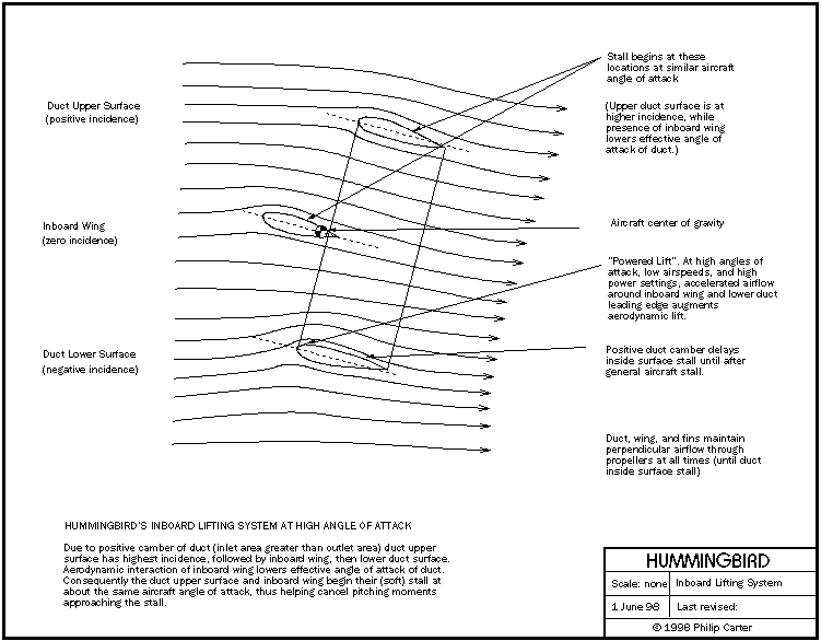
This brings us to some of the finer details of Hummingbird’s lifting system. While the duct is located a few inches behind the aircraft CG, the inboard wings are located a few inches forward. The geometry of these inboard surfaces is tailored as an integrated “soft stalling” system with minimum pitching moments through the stall and a lift curve very different to that of the outboard wings.
Due to the positive camber of the duct (inlet area greater than outlet area) the upper duct surface will have positive incidence, the lower duct surface negative. The inboard wing is at zero incidence and will lower the duct’s effective angle of attack. Thus the duct outer surface and inboard wing airfoils are designed for a soft, simultaneous stall, minimizing any pitch trim changes. The duct section in particular has an extremely soft stall, which when combined with the circular geometry will ensure that the duct remains flying well after the outboard wings have stalled, meaning that the aircraft will need to be held in a stalled condition with up elevator.
Propulsion
Objection:
“You will never get enough thrust to hover.”
Answer:
Calculations based on energy/momentum considerations and expected blade performance predict a maximum static thrust from an optimized propulsion system (using the F30, at sea level) of more than 1400 lb. This estimate is confirmed by results from the XROTOR computer program, which has facilities to model the counter-rotating, ducted configuration. Thrust levels with 150 hp engines are predicted to be around 1600 lb. These thrust estimates assume tip clearances far greater than propulsive optimums and duct geometry optimized for L/D and stall characteristics rather than for propulsion.
The fact is that Hummingbird has sufficient power to weight and propulsive efficiency to hover without a duct at all. Some conventional aerobatic aircraft do have sufficient thrust to hover, but they waste energy trying to control the torque. Hummingbird will be comfortable and efficient in the hover. It will not be a struggle.
The real issue for Hummingbird is not whether it will hover, but how fast it will climb vertically. The best current estimate for vertical climb rate is about 25 knots at sea level, dropping off to zero at a hover ceiling of about 6000 feet.
Objection:
“According to Russian experience with counter-rotating ducted fans, the two fans must be synchronized for the system to work.”
Answer:
I have heard this from more than one source, so it should be addressed. Perhaps this objection applies to the transonic realm in which the huge Russian engine was designed to operate, but there is no theoretical basis for it to apply to Hummingbird. The forward propeller sees the aft propeller simply as an induced axial velocity component added to the airflow. The aft propeller sees the forward propeller as induced axial and rotational velocities. When both engines are producing the same torque, the propulsion system will be torque free. It is as simple as that.
Objection:
“Those belts look too small to take all that power.”
Answer:
The belt width and sprocket geometry are identical to those of the well-proven Behlen drive sold by Hirth for the F30. Belts have lasted several hundred hours without problems on these drives, though a distributor has recommended replacement at around 200 hrs.
When, as expected, Hummingbird’s engines are uprated to 150-160 hp, the belts will be upgraded to a new generation of synchronous belts presently in field testing and due for release in 1998. The new belts are promised to improve power density by 50% over existing types, allowing the present 62 mm belt width to be maintained with the larger engines.
This is important for Hummingbird, since any increase in belt width would force major changes in the surrounding structures, and may even require an increase in duct chord.
Performance and Handling
Objection:
“With all those surfaces, this thing is going to be slow.”
Answer:
While Hummingbird will be slower than a similarly sized and powered monoplane, it will definitely be faster than a typical biplane. There are about 140 sq ft of airfoils on the airplane (similar to a Pitts S2B), not including the tail surfaces and winglets. It is these airfoils that make the airplane fly the way it does, so we have to live with them.
Since there is so much surface area on the airplane, the drag of that surface area must be reduced as much as possible. The wing airfoil is only about 11% thick outboard of the duct, and is being designed for laminar flow back to about 25% chord (60% chord inboard of the duct). Analytical results of current airfoils show significant drag reductions over competing aerobatic airfoils. The duct outer surface is predicted to have laminar flow to about 50% chord and relatively low drag. All airfoil intersections are at 90 degrees, while fuselage cross-sections transition smoothly through the duct, minimizing interference drag. Fuselage, landing gear, and cooling drag are low. Power to weight ratio and propulsive efficiency are high. Hummingbird’s speed will be surprising.
Objection:
“The thing may not snap worth a damn.”
Answer:
Much attention is being given to Hummingbird’s snap-roll characteristics. Wing airfoils are being designed with a very deep stall break, made possible by the relatively thin outboard wing sections. With the proper attention to airfoils and planforms, there is no reason why Hummingbird should not be a good snapping airplane.
Objection:
“The thing is so symmetrical, you won’t be able to tell whether it is knife-edge or upright, so it won’t make any difference.”
Answer:
When Hummingbird’s wings are vertical, it will be obvious that the airplane is knife-edge. Rather than diminishing the visual impact of knife-edge flight, the symmetry of the duct will draw attention to it. When Hummingbird is rolling, the duct will appear stationary, with the wings rotating around it—a fascinating visual effect.
The long landing gear legs will be the visual cue of whether the aircraft is upright or inverted.
General Issues
Objection:
“I accept that the concept will work, but it is very complex.”
Answer:
Hummingbird is complex geometrically, but in other respects it is a very simple machine. For instance: there are no flaps or retractable landing gear; the 2-cycle or Wankel engines are far simpler than their 4-cycle cousins; and the right and left wings are identical.
For the sake of comparison, the Lancair 235/320 is representative of a popular, successful, experimental aircraft kit of moderate cost. The following compares the complexity of the two aircraft by counting molds and major fabricated parts (considering just airframe, landing gear, and control systems):