Structures
The Duct as an Idealized Truss
Duct Brace Geometry
Duct Structure
Forward Fuselage Structure
Vertical Fin Structures
Stator Structures
Aft Fuselage Structures
Connecting Fwd and Aft Fuselages
Wing Structure
Tail Surface Structures
Landing Gear Structures
Overview
Critical to the success of the Hummingbird concept is the creation of exceptionally light, stiff structures. A central strategy towards attaining this is the use of advanced materials and manufacturing processes.
Modern aerobatic sequences place extreme loads on a competition airplane. A limit load factor of plus and minus 10 or 12G is considered normal. If, as is standard practice with composite materials, a safety factor of 2 is employed, this translates into 20 to 24G ultimate.
Few current aerobatic aircraft take full advantage of the weight reductions possible with modern advanced composite materials. The high strength, stiffness, and fatigue life of carbon/epoxy materials make them an excellent choice for such a weight-sensitive, highly stressed airframe. Moreover, these materials can easily be applied to the construction of complex forms, such as Hummingbird’s duct and wing.
Hummingbird’s configuration presents a very different set of structural problems, and at first sight an engineer might be forgiven for considering it a structural nightmare. It will be seen, however, that the configuration actually offers structural efficiencies over conventional configurations, without the biplane's high parasite drag cost. A projected weight breakdown is provided on our Weight and Balance page.
The Duct as an Idealized Truss
The duct is the structural heart of the airplane, since it literally connects together the major components. In fact, the configuration would not be viable without the duct structure to carry loads between the aft fuselage, forward fuselage, and wings.
A design problem which may not be immediately obvious involves propeller tip/duct clearances. Since the duct is fixed to the wing, as the wing flexes under load it will distort the duct, ultimately leading to propeller/duct contact. The converse is also true, however: If the duct can be braced to limit its distortion under load, it will also serve to brace the wing, in both bending and torsion.
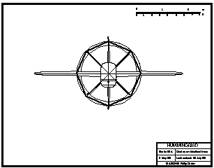
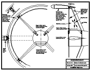
The only weight-efficient way to limit distortion of the duct is to brace it. In theory this turns out to be a rather simple task, since the major portions of the brace structure already exist. The adjacent drawing illustrates how the addition of 45-degree struts to the duct creates an extremely efficient octagonal truss (with help from the wings and ventral fins).
Theoretically, this exact structural geometry could be built using straight structural members inside the duct structure. In practice, the duct skins and shear webs sufficiently approximate this geometry that they can be designed to take the applied loads.
Duct Brace Geometry
45-degree structural braces (struts) at the duct leading edge would offer an optimized structural geometry, but they further disturb the already dirty air entering the propellers. Since propulsive efficiency is of high priority in this airplane, we are forced to investigate alternative duct bracing schemes.
The duct geometry renders it an intrinsically rigid structure. There are aerodynamic as well as structural advantages to using a thick duct airfoil—perhaps as thick as 20% t/c. Consequently it becomes possible to build sufficient torsional stiffness into the duct that it can be braced at its aft spar and resist the complex torsional loads coming from the wing. This allows stators to brace the duct at the aft spar, without the need for additional struts at all.
All present work is being focused on the 4-stator @ 45 degrees configuration. Vertical struts could be added (to create an octagonal truss at the aft duct spar) if required.
Duct Structure
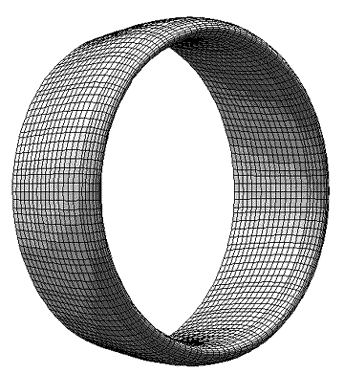
The duct skins are female-molded sandwich structures of carbon/epoxy/nomex. They could be fabricated in thirds (120-degree arc) or halves (180-degree arc), thus simplifying tooling. Three identical 120-degree arc skins could be joined during assembly, for instance, to create the entire outer or inner surface of the duct.
All primary loads are taken through the duct skins. The two circular C-section spars are essentially shear webs; they tie the stressed skins together into an efficient box structure and distribute loads into the skins from wings, ventral fins, and stators.
Attach points are reinforced by pre-cured composite hardpoints, bonded to shear webs and skins during duct assembly. The hardpoint bonds are loaded in shear only and the toroidal duct beam remains completely unbroken. The many ribs will be straightforward to manufacture since they are all identical, due to the constant chord of the duct.
Forward Fuselage Structure
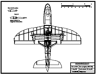
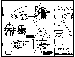
The forward fuselage structure aft of the pilot seat is based on left and right composite sandwich panels. Bulkheads transfer loads from the wing and ventral fin attach points, while supporting the forward engine and the forward end of the propeller axle. The forward engine, wing spar, main landing gear, ventral fins, propeller axle, pilot seat, sump tanks, and BRS are all in close proximity, resulting in short load paths and an efficient structure.
The fuselage structure forward of the seat is lightly loaded, and the worst-case design scenario is for pilot protection. Two composite beams double as consoles/control routes down the sides of the cockpit and are tied together by the seat structure and again forward of the rudder pedals. These beams approximate triangular box-spars of about 7 inch x 4 inch cross-section, and are being designed to provide protection to the pilot in the case of a roll-over or crash. They also support the canopy tracks, instrument console, rudder pedals, and forward sight. This arrangement minimizes structural bulk so that visibility is optimized. The entire primary structure of the forward fuselage will be assembled from just three large molded parts (left, right, and internal) and a few flat bulkheads.
Ventral Fin Structures
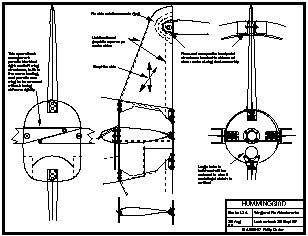
The ventral fins structurally connect the forward duct spar to the forward fuselage. Since the wing absorbs all torsional loads between the forward fuselage and duct, the ventral fins are asked to take only bending and shear loads in-plane, which they can do very efficiently. Nevertheless, in order to maintain alignment between the forward engine and propeller axle it is necessary to design very high stiffness into the ventral fins, utilizing carbon fiber spars at the leading and trailing edges, with a solid foam core and carbon skins to tie the spars together and stabilize them against buckling.
Stator Structures
Like the ventral fins, the stators are loaded predominantly in-plane to transfer bending loads between the aft fuselage and duct, and must be designed to similarly rigorous stiffness criteria. Unlike the ventral fins, however, the lower stators are also loaded in bending normal to the chordline in order to transfer torsional loads between the aft fuselage and duct. Thus there is the potential for buckling of the trailing edge under combined compression and bending loads. Consequently the aft spar cap is brought forward from the trailing edge to increase its thickness and resistance to buckling. As with the fins, solid foam cores and carbon skins stabilize and tie together the stator spars and complete the aerodynamic form.
The ventral fins and stators are perhaps the must unorthodox and demanding structures to be found on the airplane. Nevertheless, calculations indicate that the depicted structural schemes will allow the creation of adequate longitudinal stiffness between forward and aft fuselages.
For those who wonder about the fins or stators “not being strong enough”, it should be noted that when adequate stiffness is designed into the fins and stators, they will never see more than 20% of allowable stresses.
Aft Fuselage Structure
The aft fuselage boom is a simple, tapered, composite tube, molded in carbon/epoxy with nomex cores. The stabilizer, fin, and lower stators are permanently bonded into the boom with the help of internal bulkheads.
Connecting Forward and Aft Fuselages
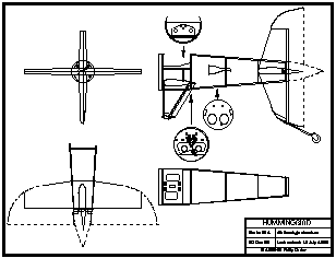
The structural arrangement of the fuselage around the propellers and duct requires a conceptual leap. It should be emphasised that NO fuselage loads are taken through the propeller axle. All fuselage loads are taken AROUND the propellers, through the duct, via the stators, wing, and ventral fins. Thus, one could remove the props and axle and have a structurally complete fuselage (with a large gap in the middle). Now, attach a large-diameter metal alloy tube into the gap between the fore and aft fuselages at the rotational axis. This is not a shaft, because it doesn’t rotate. I call it an axle. The propellers rotate on the axle.
Wing Structure
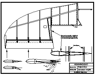
The wing skins are sandwich structures built in female molds from carbon/epoxy/nomex. Main spars are carbon C-beams, possibly autoclaved. Since the spars are only about 10 ft in length, autoclaving would not add great expense, but there may be little to gain since the spars are so lightly loaded.
Due to the braced configuration there will be little weight penalty resulting from using a two-piece main spar. The spars overlap each other across the fuselage and connect into a bulkhead. This ties the wing and duct into the fuselage torsionally (on the roll axis). The wing trailing edge attaches to the aft bulkhead, thus tying the wings and duct into the fuselage on the yaw axis.
The two-piece main spar will allow the aircraft to break down for shipping so that the largest component is only about 10 feet in length.
Hummingbird’s structural configuration will allow for major weight savings in the wing structure. Due to its small size and efficient bracing system, this will be the lightest wing of any unlimited class aerobatic machine. At the same time, the wing airfoil at the wing/duct intersection is only 11% thickness/chord.
Hummingbird’s wings will be aerodynamically and structurally symmetrical. Right and left wing skins and spars will therefore be identical, so they can be built in the same tooling.
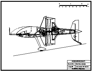
Tail Surface Structures
Since their internal volumes are very low, the tail surfaces and winglets may well be as light, and more durable, if built by moldless techniques over foam cores, using glass or carbon fibers. Considering the complex planforms, however, production parts will likely be built up from female-molded carbon/epoxy/nomex skins.
Landing Gear Structure
The main landing gear legs are quite long (about the same length as the Sukhoi SU26/31 titanium gear), so significant gains could be realized by optimizing their structural efficiency. One solution is a carbon/epoxy gear cured in two parts (top and bottom) in an autoclave. These halves are then joined at leading and trailing edges (possibly with an internal shear web), and torsional layups added, creating a hollow, tapered component of very high structural efficiency.
The main gear legs are in two pieces, left and right, to simplify dismantling for transport.


© Copyright 1992-2009 Philip Carter
